
Network Backbone: Planning and Sizing the Passive Infrastructure for High Availability
In an increasingly demanding environment in terms of performance and service continuity, passive infrastructure plays a central role in the reliability of communication networks. While investments often prioritize active equipment, it is the physical layer — cabling, connectors, conduits, and telecom racks — that provides the foundation for true high availability.
The network backbone is the structural element that interconnects critical areas such as racks, buildings, or data centers. Its effectiveness depends on precise planning, appropriate technological choices, and the strict application of installation and certification best practices. This article examines the key aspects of planning and sizing the passive backbone infrastructure, focusing on physical redundancy, scalability, and standards compliance, while also highlighting barpa’s pre-assembled solutions in copper and optical fiber.
Key Passive Components
Copper Cabling
• Copper remains a valid solution for short-distance backbone links, especially within telecom rooms or between racks located in the same building.
• Category 6A: Widely adopted standard, supports 10G over Permanent Links up to 90 meters.
• Category 7: Enhanced performance, often used with Category 6A RJ45 connectors for full compatibility with Ethernet equipment.
• Category 8: Designed for 40G, suitable for channels up to 30 meters. Excellent option for data center backbones, especially for rack-to-rack mirroring (spine-leaf topology), where low latency and high bandwidth are critical.
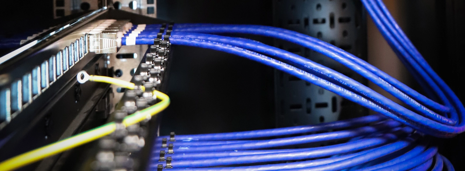
barpa’s pre-assembled copper solutions offer:
• Fast and error-free installation, with factory-terminated and tested connectors.
• Elimination of on-site crimping, significantly reducing installation time and material waste.
• Clear labeling and identification by channel, ensuring full traceability and future scalability.
• Channel certification included, with testing according to international standards: ISO/IEC 11801-1, ANSI/TIA-568.2-D, and EN 50173-1, guaranteeing system performance.
Optical Fiber
Fiber selection in the backbone must consider distance, bandwidth, and network architecture. OM1 and OM2 fibers are now considered obsolete for new deployments due to performance limitations and incompatibility with 40G and 100G applications. While still present in legacy infrastructures, they have been surpassed by more efficient and scalable technologies.
Recommended options for modern infrastructures include:
OM3 (Multimode – 50/125 µm)
• 1 GbE: up to 800 m
• 10 GbE: up to 300 m
• 40 GbE / 100 GbE (SR4, BiDi): up to 100 m
• 40 GbE SWDM: up to 240 m
• 100 GbE SWDM: up to 75 m
Ideal for enterprise environments and data centers requiring medium distances and high throughput.
OM4 (Multimode – 50/125 µm)
• 1 GbE: up to 900 m
• 10 GbE: up to 550 m
• 40/100 GbE (SR4, BiDi): up to 150 m
• 40 GbE SWDM: up to 350 m
• 100 GbE SWDM: up to 100 m
An optimized version of OM3, with higher modal bandwidth and better SWDM performance.
OM5 (Wideband Multimode – 50/126 µm)
• 1 GbE: up to 900 m
• 10 GbE: up to 550 m
• 40/100 GbE (SR4, BiDi): up to 150 m
• 40 GbE SWDM: up to 440 m
• 100 GbE SWDM: up to 150 m
Designed for wavelength multiplexing (SWDM 850–950 nm), enabling higher bandwidth with fewer fibers. Ideal for high-density data centers and spine-leaf topologies.
OS2 (Singlemode)
Singlemode fibers are the standard choice for long distances and backbone links between buildings, across campuses, or in critical infrastructure.
Supports:
• 1G to 100G and beyond, depending on transceiver type
• Distances over 10 km with stable performance and very low attenuation (<0.4 dB/km at 1310 nm)
Ideal for permanent links between main distribution frames (MDFs), buildings or remote data centers, ensuring future scalability.
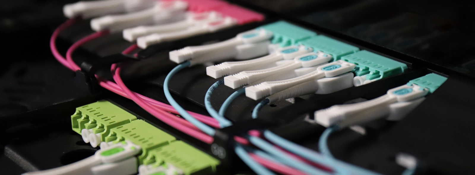
The implementation of pre-terminated fiber optic solutions, such as those provided by barpa, offers multiple advantages:
• Reduced installation time and complexity.
• Industrial-grade terminations with polishing, inspection, and testing.
• Elimination of incorrect pairings or excessive losses.
• Available in MPO, LC, and SC formats, with per-channel labeling and technical documentation.
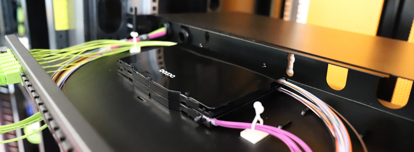
Patch Panels and Racks
• Essential elements for backbone termination, organization, and management. Modular patch panels enable quick interventions and reconfigurations without compromising system integrity.
• Properly sized and ventilated racks, with designated areas for copper and fiber, enhance system reliability and facilitate maintenance.
• It is essential to reserve at least 30% of available space in each rack, in both rack units (U) and cable management capacity. This margin ensures flexibility for future expansions without the need to modify or replace existing racks.
Trays, Organizers, and Cable Pathways
• Metal or fiber trays, PVC Raceway systems, and other conduits must be carefully sized and installed, ensuring adequate physical separation between different cable types.
• It is critical to ensure:
1. Separation between copper and fiber optic cables.
2. Above all, separation between data cables and power cables, to prevent electromagnetic interference (EMI) and meet regulatory requirements. This separation can be achieved using dedicated compartments, metal dividers, minimum spacing, or completely independent routing systems, depending on the installation.
• The minimum bending radius, installation slack, and mechanical load limits for each cable type must also be observed, maintaining physical integrity over time.
• To guarantee infrastructure scalability, a minimum of 50% free space in trays, raceways, and cable paths is recommended, allowing for future expansions without affecting the existing system.
• The use of vertical and horizontal organizers, as well as standardized and durable labeling, improves installation legibility, reduces operational errors, and significantly enhances infrastructure management throughout its lifecycle.
Common Physical Topologies in Fiber Optic Networks
The physical topology of the backbone has a direct impact on the resilience of the infrastructure and its fault tolerance:
• Simple Star: Each secondary rack connects directly to the main rack via a single physical path, creating a single point of failure.
• Ring Topology: Racks are connected sequentially in a closed circuit. In the event of a failure in one segment, traffic is rerouted in the opposite direction, ensuring continuity.
• Star with Ring Redundancy: Combines a star architecture with ring-style cross-links between racks, offering full physical redundancy and greater fault tolerance.

Physical redundancy must be ensured by using truly independent routes, preferably installed in separate conduits or infrastructure, with minimum spacing between parallel paths to reduce the risk of simultaneous failure caused by localized events such as accidental cuts, water infiltration, or fire.
Best Installation Practices
Passive infrastructure installation must follow strict quality standards to ensure long-term performance and reliability:
• Respect the minimum bending radius, based on the cable type and jacket, especially for cables intended for indoor installations.
• Avoid using over-tightened serrated zip ties, which can cause repeated deformations along the cable, resulting in extrinsic attenuation and degraded performance. As a best practice, the use of Hook and Loop Fastener should be preferred, as they provide secure fastening without excessive compression and facilitate future interventions.
• Do not exceed the allowed pulling force during installation, as defined by the manufacturer. Excessive tension, whether on fiber or copper pairs, causes irreversible damage, requiring full cable replacement.
• Keep cables organized, ventilated, and properly supported, using vertical and horizontal cable managers.
• Label all cables, conduits, and racks clearly and consistently, using standardized, durable tags.
The success of any network infrastructure starts long before the first data packet is transmitted. It begins with design, the quality of materials, meticulous execution, and, above all, with the awareness that passive infrastructure is critical to ensure high availability, consistent performance, and system longevity.
The adoption of engineering best practices, combined with technological solutions such as barpa’s certified pre-assembled systems, not only reduces installation time and errors in the field but also significantly increases network reliability in demanding environments.
Ongoing training of technical teams, including designers, installers and maintenance personnel, is equally essential. Only with solid knowledge of standards, methods and physical system limitations is it possible to ensure technically correct and sustainable installations over time.
Sorry, the comment form is closed at this time.