5 Steps to Ensure Quality and Compliance in Structured Cabling Certification
In corporate environments that increasingly depend on connectivity, structured cabling infrastructure becomes one of the fundamental pillars for ensuring the efficient operation of systems, applications, and critical services. Whether in a small company or a large Data Center, the quality of the communications network directly impacts operational performance.
Among all network components, the network cable plays a central and often underestimated role. Unlike switches, routers, or servers, which are regularly replaced or upgraded, the cable is installed during the building’s construction phase or infrastructure renovation and remains in conduits and cable pathways for decades, often for the entire lifespan of the building. For this reason, selecting the appropriate type of cable and installing it according to best practices are decisive factors to ensure a network prepared for both present and future demands.
However, merely installing network cables, whether copper or fiber optic, is not enough. To ensure the infrastructure meets performance requirements and international standards, it is essential to test and certify all network points.
This practical guide aims to clarify what it means to test and certify a structured cabling system, present the most common types of tests, explain the applicable standards, and offer practical tips to ensure a secure, stable, and future-ready network.
1.What is Structured Cabling Testing and Certification
Testing and certifying a structured cabling system is a fundamental process to ensure that all infrastructure components, from cables, connectors, outlets to patch panels, are properly installed and that the system meets the performance requirements defined by international standards.
Testing refers to the technical verification of installation parameters such as continuity, signal loss, interference, and cable length. These tests can be carried out during or after installation to validate the quality of materials and workmanship.
Certification, on the other hand, involves issuing a technical report validated by calibrated, industry-recognized equipment, which proves that the network has been tested and complies with specific standards (such as ISO/IEC, ANSI/TIA, or EN). This process is generally required in professional projects and may be a condition for activating manufacturer warranties.
Beyond ensuring proper network performance from the outset, certification offers several important benefits:
• Minimizes future failures, avoiding costly rework;
• Confirms compliance with standards, which is essential in critical projects;
• Facilitates maintenance and network expansion with clear documentation;
• Enhances the integrator’s credibility, adding value to the service provided;
• Protects the end customer’s investment, ensuring long-term performance.
Testing and certification must always be carried out using appropriate equipment with valid calibration certificates, by qualified technicians, following rigorous procedures and complete documentation. This approach ensures that results are reliable and recognized by both manufacturers and technical auditors, ensuring compliance and professional-quality installation.
2.Standards and Technical Categories
The certification of structured cabling systems depends on compliance with internationally recognized technical standards. These standards define the minimum requirements for performance, safety, and interoperability, in both copper and fiber optic systems. Understanding them is essential to ensure compliance and guarantee the quality of the installed infrastructure.
Key Standards:
- ISO/IEC 11801 – International standard for generic cabling in commercial, industrial, and residential environments.
- ANSI/TIA-568 – American standard defining the cabling requirements for telecommunications, widely used in global projects.
- EN 50173 – European standard that establishes performance and interoperability requirements for structured cabling systems.
These standards specify, among other aspects:
- The types of cables and connectors allowed;
- Recommended installation methods;
- Electrical and optical performance limits;
- Maximum distances allowed depending on the physical medium (copper or fiber);
- The admissible topological configurations for cabling systems, including the hierarchy of subsystems: Campus Distribution Backbone, Vertical Distribution Backbone, and Horizontal Distribution, an special attention deserve consolidation points and WiFi coverage zones;
- Conditions for electromagnetic compatibility (EMC).
Copper Cabling Categories
The categories define the performance of twisted pair cables in terms of bandwidth and support for network applications. In modern projects, it is essential to consider not only current performance but also the scalability of the infrastructure.
The most common are:
- Cat.5e – Up to 100 MHz, suitable for 1 Gbps networks.
Officially removed from international standards ISO/IEC 11801-1 in the 2017 edition, with a subsequent update in 2021, and no longer recommended for new installations. - Cat.6 – Up to 250 MHz, with better performance and lower interference compared to Cat.5e. Although still in use, it is becoming insufficient for environments with higher device densities and 10 Gbps requirements.
- Cat.6A – Up to 500 MHz, ideal for 10 Gbps (10GBASE-T) over distances up to 100 meters (channel). Recommended as a minimum for new installations aiming at sustained performance and future-proof applications.
- Cat.7 / Cat.7A – Between 600 and 1000 MHz, with individual shielding per pair and overall shielding. Used in specific applications that require high immunity to noise, they employ connectors standardized by ISO/IEC, such as GG45 or TERA, which are not compatible with RJ45 modules.
However, GG45 modules are backward compatible with RJ45 plugs, allowing the use of standard RJ45 patch cords. Conversely, GG45 plugs cannot be inserted into RJ45 sockets due to construction differences and additional contacts.
- Cat.8 – Up to 2000 MHz, supporting 25 Gbps and 40 Gbps over short distances (up to 30 meters in a channel).
Recommended for high-speed links in data centers, such as switch-to-switch or switch-to-server connections.
Each category corresponds to a performance class:
- Class D – Cat.5e
- Class E – Cat.6
- Class EA – Cat.6A
- Class F / FA – Cat.7 / Cat.7A
- Class I / II – Cat.8.1 / Cat.8.2
3.Copper Testing Parameters
Copper cable testing is essential to validate compliance with applicable standards (TIA/ISO/EN) and to ensure that the infrastructure will support the desired transmission speeds. These tests are performed using certification equipment that evaluates various electrical parameters of the links.
Main tests performed on copper cabling:
- Wire Map: Verifies whether the conductors are correctly connected at both ends. Detects crossed, reversed, shorted, open, or split pairs.
- Length: Measures the total electrical length of the link, based on the signal propagation time and the cable’s Nominal Velocity of Propagation (NVP), which is the percentage of the speed of light at which the signal travels in the medium. Incorrect NVP settings on the tester may result in inaccurate cable length readings.
- Delay Skew: Measures the time difference for signal propagation between cable pairs. A well-installed infrastructure should ensure skew below 50 ns over a 100-meter channel. High values may impact signal synchronization, especially in Gigabit and faster networks.
- Resistance: Evaluates the electrical resistance of conductors. High resistance may affect performance and PoE operation.
- Insertion Loss: Measures the difference in signal power between the input and output, expressed in decibels (dB). Increases with cable length and frequency, and directly affects received signal strength.
- Return Loss: Measures the amount of signal reflected to the source due to impedance variations. Excessive reflections compromise signal integrity and stability. Expressed in dB.
- NEXT (Near-End Crosstalk): Also known as near-end crosstalk, it measures interference on an adjacent pair caused by a signal applied at the same end. Expressed in dB.
- PS NEXT (Power Sum Near-End Crosstalk): Calculates the total crosstalk one pair generates on the other three pairs. This is a calculated, not measured, value.
- ACR-N (Attenuation to Crosstalk Ratio – Near-End): Represents the relationship between the transmitted signal and crosstalk measured at the near end. Calculated as NEXT minus insertion loss. The higher the value, the better the signal margin.
- PS ACR-N (Power Sum Attenuation to Crosstalk Ratio – Near-End): Measures the ratio between signal attenuation and crosstalk (NEXT), serving as a direct indicator of signal-to-noise margin. Higher ACR values (in dB) mean a stronger signal relative to interference, reducing the risk of data errors.
- ACR-F (Attenuation to Crosstalk Ratio – Far-End): Indicates the difference between the received signal strength and far-end crosstalk (FEXT). Higher values (in dB) provide better signal integrity in bidirectional communications.
- PS ACR-F (Power Sum Attenuation to Crosstalk Ratio – Far-End): Measures the difference between the total far-end crosstalk from all pairs (PS FEXT) and the signal attenuation. Higher PS ACR-F values indicate greater resilience against crosstalk in bidirectional transmissions.
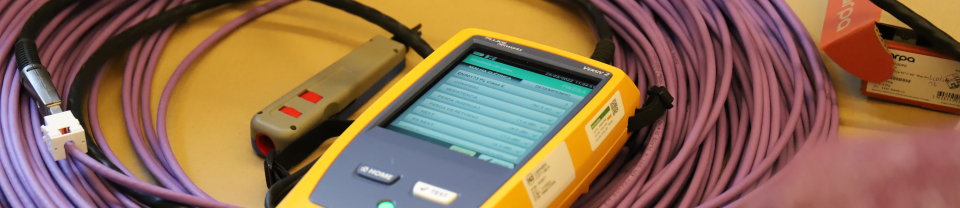
Recommended Equipment
For certification purposes, professional-grade equipment is recommended, such as the Fluke Networks DSX Series, Ideal Networks, among others. These devices generate certification reports that verify compliance with applicable standards and can be used to validate warranties with cabling manufacturers.
4.Types of Tests for Optical Fiber
The certification of fiber optic links is essential to ensure data transmission occurs with minimal signal loss and maximum reliability. Installation quality, connector cleanliness, and correct component selection directly impact the performance of the optical network.
- Multimode (MM): OM3, OM4, OM5 – Optimized for 10/40/100 Gbps applications, ideal for LAN and Data Center environments.
Note: OM1 and OM2 have been removed from current specifications as they no longer meet the bandwidth requirements of modern networks.)
In multimode fiber certification (OM3, OM4, OM5), optical loss tests (OLTS) should be performed in two wavelength windows:
- 850nm – Main operating window for multimode applications.
- 1300nm – Used to verify behavior over longer distances and ensure attenuation stability along the fiber.
Note: Multimode fiber performance is more sensitive to geometric variations in the core, especially at 1300nm, where fewer propagation modes exist. For this reason, measurements at both windows (850nm and 1300nm) are essential to ensure more reliable results. Ensure compliance with ISO/IEC 14763-3, TIA-568.3-D, and EN 50173-1 standards.
Singlemode (SM):
- OS1a, OS2 – Suitable for long distances with low attenuation. Widely used in backbones, campuses, and inter-building links.
- OS1a: For indoor installations, with improved performance over the original OS1.
- OS2: Suitable for indoor and outdoor installations, especially ideal for long-distance links with low attenuation.
In singlemode fiber certification (OS1a, OS2), optical loss tests (OLTS) should be performed at two wavelengths:
- 1310nm – Used for point-to-point transmissions and to characterize the fiber in the low dispersion range.
- 1550nm – Sensitive to bends and used to evaluate excessive losses in critical or poorly installed areas.
Note: Measurement at 1550nm is especially important in long-range networks or indoor installations where excessive bends may cause significant losses that go undetected at 1310nm. Ensure compliance with ISO/IEC 14763-3, TIA-568.3-D, and EN 50173-1 standards.
Testing and Certification Equipment
- Optical Loss Test (OLTS): Measures the total attenuation of a link using a stable light source and an optical power meter. It checks whether the loss is within the limits recommended by standards, considering the link length, splices, and connectors. It is the most common certification test.
- OTDR (Optical Time Domain Reflectometer): An advanced testing device that accurately locates events along an optical fiber, such as splices, connectors, excessive bends, breaks, or continuity faults. The OTDR sends light pulses and analyzes the reflected signals to identify the location of each event. It allows point-to-point optical power loss measurement, identification of high-attenuation zones, and detection of excessive reflections. It is an essential tool for diagnostics, preventive maintenance, and fault resolution.
Note: In addition to inspection, it is highly recommended that technicians have a portable kit consisting of a light source (injector) and an optical power meter.
This set allows for quick optical loss measurements during spot checks or basic continuity tests, without the need for advanced equipment. It is an effective solution for immediate field validations.
Fiber testing requires specialized equipment, such as:
- OLTS (Optical Loss Test Set) – e.g., Fluke CertiFiber Pro, EXFO MAXTester
- OTDR – e.g., EXFO, Yokogawa, VIAVI
- Digital inspection microscopes, with automatic compliance analysis (IEC 61300-3-35)
Best Practices Before Testing
- Connector Endface Inspection: Before any measurement, visual inspection of the connector endfaces using an inspection microscope is mandatory. The presence of dust, scratches, or residues can severely compromise the quality of the link and cause signal loss, excessive reflections, or even permanent damage to active equipment (transceivers).
- Thorough Cleaning: Clean the contact surfaces (connectors and adapters) with appropriate cleaning kits. Avoid using non-specific materials such as regular cloths, tissue paper, cotton, or generic wipes, as they may leave residues, particles, or cause microscopic scratches that compromise the connection.
- Safety Warning: When using analog microscopes, there is a risk of direct exposure to laser radiation. To avoid eye injury, always ensure both fiber ends are disconnected and never look into an active link.
Technical Report
After completing the tests, it is essential to organize a comprehensive technical report, including:
- Project and client identification;
- Name of the responsible technician and executing company;
- Testing equipment used (brand, model, and serial number);
- Valid calibration certificate;
- Applied testing standard (TIA, ISO/IEC, EN);
- Results for each tested point (Pass/Fail);
- Detailed graphs or measurements (e.g., OTDR, RL, NEXT, IL);
- Network point identification map.
In addition to ensuring transparency, this documentation allows full traceability of the infrastructure, facilitating future interventions such as layout changes, expansions, and audits.
5.Cabling System Warranty
Leading structured cabling manufacturers offer long-term warranty extensions, often between 15 and 25 years, to ensure the reliability, performance, and compliance of the infrastructure throughout its lifecycle.
Example: barpa 25-Year Warranty
barpa provides a 25-year warranty on the structured cabling system, provided the following requirements are met:
- The entire solution is composed of barpa components, including cables, connectors, panels, racks, and structural accessories;
- Installation is carried out by a barpa-certified integrator, with technical training recognized by the brand;
- Certification tests are conducted with testing equipment bearing valid calibration certificates issued by the respective manufacturers;
- Complete technical documentation of the installation (including test reports) is submitted to barpa and approved according to the brand’s criteria.
In addition, the specialized technical training of the professionals involved contributes directly to:
- The reduction of failures and rework;
- Easier future maintenance;
- Access to extended manufacturer warranties, if installation, testing, and documentation criteria are met.
This technical rigor translates into tangible benefits for both integrators and end customers:
- For the integrator, it represents a mark of quality and market differentiation;
- For the customer, it means peace of mind, investment security, and extended support over the years.
Testing and certifying structured copper and fiber optic networks is not just a technical requirement, it is an essential practice to ensure the quality, reliability, and longevity of the communication infrastructure. By following international standards, using calibrated equipment, and applying proper installation practices, it is possible to ensure that the network will be ready to support present and future applications with high performance.
Sorry, the comment form is closed at this time.